
Axis Calibration Building Block
The Axis Calibration building block is used to interpolate a Number value from one range of values into a new range of values. It is commonly used to create a value that is used with a Virtual Axis building block.
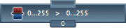
An Axis Calibration building block has one Number input and one Number output. The output value is calculated based on the input value and the building block' s configuration.
To configure an Axis Calibration building block, enter the expected input range and the desired output range into the Inspector window.
The limits of the expected input range define the minimum and maximum values that the building block expects to receive. For example, if the Axis Calibration building block is connected to an Axis building block, and the corresponding controller axis produces value in the range 23...247, then the lower and upper limits of the expected input range would be 23 and 247 respectively.
The limits of the desired output range define the values that the Axis Calibration building block should create. If the output will be used to control a joystick Virtual Axis building block, the output range will typically be 0...255. If the output will be used to control a mouse Virtual Axis building block, the output range will typically be -40...40, -30...30, -20...20, or something similar depending on the desired speed of the virtual mouse.
When the input of the Axis Calibration building block is at (or below) the expected minimum input value, then the output will be set to the minimum calibrated output value. Similarly, when the input of the building block is at (or above) the expected maximum input value, then the output will be set to the maximum calibrated output value.
Normally, as the input values get larger, the output values will also get larger. To reverse this operation (to make the output value get smaller as the input value get larger), swap the values in the calibrated output range.
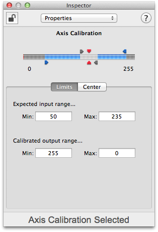
In the Inspector window, dragging the blue arrows in the control will change the expected input range.
In the example to the right, the building block expects to receive values in the range 50...235. When the input value is at (or below) 50, the output will be set to 255. When the input value is at (or above) 235, the output will be set to 0. In this configuration, the output values will get smaller as the input value gets larger.
If the input value has a natural center point, then turn on the Center Value under the Center tab in the Inspector window. Typically, joystick and gamepad X and Y axes will rest at their center locations. Sliders, dials, and other axes may not have a specific center value.
When a center point is used, a deadband can also be set. The deadband defines the how close the input value needs to be to the center value to be considered "centered". A deadband is useful if the axis does not always return to exactly the same center point.
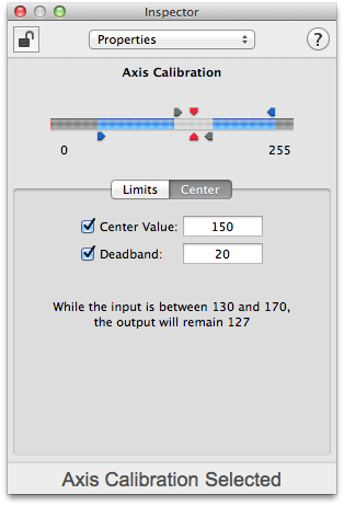
In the Inspector window, dragging the red arrows (or in the control between the red arrows) will change the center point. Dragging the gray arrows will change the size of the deadband. Dragging one gray arrow will also cause the other to move to keep the deadband centered at the center value.
In the example to the right, the building block will use 150 as the center value with a deadband of +/- 20. As the Inspector window indicates, with these center and deadband settings, while the input value remains between 130 and 170, the output will remain 127 (half way between the minimum and maximum calibrated output values).
The expected input minimum and maximum values as well as the center value (if enabled) can be found by using the calibration sequence under the "Calibrate" tab in the Inspector window. To begin, click the "Start" button under the "Calibrate" tab in the Inspector window. If the center value is enabled, you will be asked to move the axis to the center point. Do so then click on the "Set Center" button. Next, move the axis through its range of motion to discover the minimum and maximum values. When finished, click the "Set Range" button. To record the new values, click the "Save" button.
For examples of how the Axis Calibration building block can be used, see the sections on Virtual Mouse, Virtual Mouse, Virtual Joystick, and the Programming Examples.